- Published 16 Jun 2023
- Last Modified 29 Aug 2023
- 8 min
What is RCD Testing?
RCD testing is a legally-required process for circuits and appliances. Find out all about how to do it right in this guide.

Whether you’re building a circuit or checking a fuse box, RCDs are essential to protecting electrical systems, appliances, and the people using them. RCD testing is the process of checking that the RCD installed in a circuit works correctly. It can also help electricians or circuit builders identify when an incorrect RCD type has been used.
RCD testing can be completed using the test button on an appliance or fuse box. It can also be completed using a loop or RCD tester in a circuit. When running the test, a correctly functioning RCD will cut power to the appliance or circuit being checked under certain conditions within a certain time.
If this isn’t the case, then the RCD may need to be changed or there could be a fault with the appliance or circuit itself. By testing RCDs according to set procedures, under legislative guidelines, and by a qualified electrician, electrical equipment or circuits can be safely operated.
This article will explain everything you need to know about RCDs and how they are used in testing safety.
What Does RCD Stand for?
RCD stands for Residual Current Device. This describes their function as a tool that monitors the flow of electrical currents through circuits and appliances, detects when residual current is moving somewhere incorrectly, and cuts the power within a short amount of time.
How Do Testers Use RCDs in their Work?
Testers and testing play a crucial role in the safety and reliability of electrical systems, circuits, and appliances.
RCDs can perform different types of tests. A trip time test measures the time taken for the RCD to cut power off when a fault occurs. This is a key indicator that the RCD is fast enough to prevent safety hazards like shocks. A ramp test instead gradually increases the current flow to identify if it’s functioning correctly and providing an adequate level of protection.
These processes are vital to accident and injury prevention. In using RCDs, testers can and do save lives and protect valuable infrastructure.
Example of an RCD Testing Process
The process of working with RCDs requires a methodical approach to testing procedures. Here is an example of some of the steps usually involved in this process:
- Visual inspection: Typically an RCD tester would first examine the device for signs of damage or wear and tear. This would include looking for signs that connections are insecure or that the device is properly installed
- Testing method selection: A tester will need to select the appropriate method for testing based on the type of RCD and any specific system requirements
- Conduct testing: The tester will perform the appropriate testing procedure using their required training and PPE safety equipment. For example, if trip testing was conducted, a fault would be applied to the current of the RCD. The time taken for the device to trip and cut off the power would be measured and recorded
- Evaluate the results: Finally, the tester will analyse the resulting data and determine if further testing or action is required
What Does RCD Do?
RCDs are installed into circuits or devices to protect equipment, systems and people from dangerous arcs or spikes in electrical power. It does this by monitoring where electrical current is passing through and cuts the flow of power when it detects it moving somewhere it shouldn’t be.
For example, if an appliance has a live and neutral wire of which current should be moving in and out as part of a circuit, then the level of current passing through both wires should be the same. If an RCD detects that the current is not the same and therefore could be flowing elsewhere, such as in the earth wire, then it cuts the power flow.
This prevents any electricity from flowing to the wrong place, causing faults in a system or being potentially dangerous to those using the circuit or appliance.
How Does an RCD Work?
RCDs are installed into a circuit with both the live and neutral wire passing through it. Both wires are connected to coils that are wrapped around the iron core of the RCD. As such, when power is passing through these wires, a magnetic field is created by each of them.
When the electrical current passing through each wire is the same, the magnetic fields are also equal and neutralise each other. As a result, the iron-panelled switchgear next to the device’s iron core doesn’t react and the appliance or circuit can function as normal.
However, if the current in the returning neutral wire drops, then the magnetic field will also reduce. This will cause an imbalance in the fields, attracting the iron panel of the switchgear towards the iron core and breaking the circuit automatically.
To reset the RCD, a switch or button has to be pressed to reset the switchgear before the appliance or circuit is made live again. If the fault continues, the RCD will continue to be triggered by the magnetic field’s imbalance.
It should be noted that though the basic function of all RCDs is the same, there are different types of RCDs which are designed to detect different types of currents or be used in particular circuits or appliances.
- Type AC devices can only detect sinusoidal alternating currents (therefore can only be used in AC circuits)
- Type A can monitor pulsating direct currents as well as sinusoidal alternating ones making them suitable for use in single-phase appliances or loads
- Type F RCDs can be used in AC or DC circuits and are specifically designed to be installed in circuits where single-phase variable speed drives are used, meaning they won’t be triggered by changes in frequency
- Type B devices can cover all the above needs plus be used in circuits alongside three-phase rectifiers. This makes these RCDs the most useful in complex or commercial applications
- Fixed devices are, as the name suggests, permanently put into a circuit such as in a fuse box or consumer unit
- Socket-outlet RCDs are placed in specially-designed sockets to give extra protection to the appliances plugged into them and therefore the people using the appliance
- Portable devices are installed in appliances and devices, meaning they help keep this equipment and those using it safe when its plugged into a standard socket
When installing or testing an RCD, it’s important to keep the type of device in mind to ensure the circuit complies with regulations and will work effectively.
RCD Testing Protection Regulations
In the UK, the most recent RCD protection regulations are set out in the 18th Edition Wiring Regulations. Alongside wearing the right PPE and ensuring only qualified electricians or professionals are working with RCDs, these regulations set out the safety requirements for using these devices effectively.
The regulations have been updated to enhance the safety of modern systems, circuits and appliances with extra guidance including:
- The maximum current leakage under standard operations shouldn’t be any more than a third of a device’s tripping current rating
- Using type A RCDs as a minimum requirement in socket circuit outlets and fixed DC equipment
- Surge Protection Devices (SPD) should be fitted when a consumer unit is replaced or installed or according to the guidance set out in the 18th Edition
- Arc Fault Detection Devices (AFDD) are required in socket outlets up to 32A in specific domestic installations such as kitchens, bathrooms and outdoors
- RCD protection is now a requirement for any circuits which supply luminaires or portable equipment that’s used outdoors
To get a full understanding of the UK’s RCD protection requirements, be sure to check the 18th Edition guidelines.
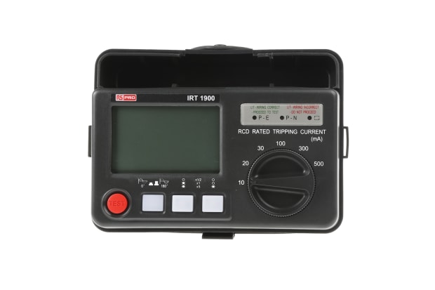
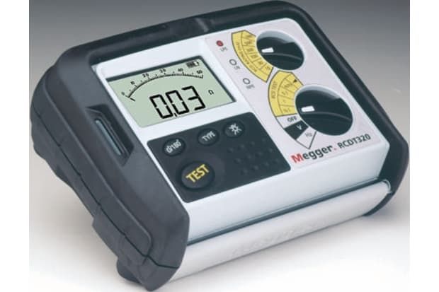
Should You Choose a Loop or RCD Tester?
Though both loop and RCD testers are used by qualified electricians to analyse the current flow and assess any faults in a circuit, they test different operations within a system. A loop tester is designed to check the function of the earth connection and ensure any fault current passing through the system will be strong enough to trigger the circuit protection.
In contrast, an RCD tester checks the performance of an RCD device at different power levels (50%, 100% and 500% at both 0 and 180 degrees) to ensure it will function correctly in the case of a fault.
Both devices can be used to determine whether the trip time and function of the RCD fall in line with regulations. However, RCD test results need to fall in line with BS 7671 regulations for a circuit to be certified as safe to use. Therefore it’s essential that you use an RCD tester to check a circuit’s safety, with a loop tester as a backup if required.